Today I was cleaning up a couple of Cox engines that have the early
crankshafts with a threaded end rather than drilled & tapped end.
They are rather notorious for bending and breaking.
The one on the Thermal Hopper I was working on happened to be bent.
I did not have a spare so decided to straighten it.
Thought I would share how I did it here.
Doing this does require a dial indicator. Now-a-days decent ones can be picked up cheap.
I have used this method for straightening bent cranks on a few different
engines with good success. I am not a
machinist by any means and this is probably not a text book method so if
you are going to try it do so at your own risk.
I have searched for information on how to straighten cranks but had no luck.
If anyone has any suggestions for alternate methods please share them.
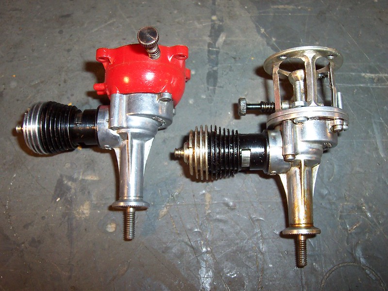
The Thermal Hopper is the engine on the right. The other is a Space Bug Jr.
The cranks are interchangeable. The bend was bad enough to be visible
when the crank was rotated.
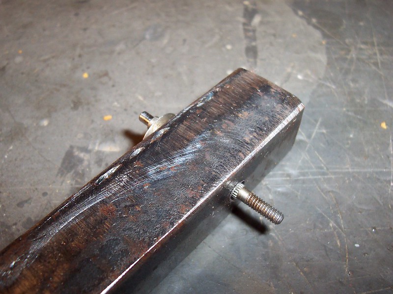
To start a fixture must be made to hold the crank.
The crank must be able to rotate with no side play.
The fixture should be thick enough that when the thrust bearing surface
is against one side only the threaded end protrudes from the other.
This crank has about a 3/16" diameter so I drilled a 3/16" hole in a
piece of 3/4" square tubing. (It is actually 2 pieces of 3/4" angle iron
welded together.) A solid piece would have been a better choice
as it would better support the full length of the crank.
The 3/16" hole had to be reamed just a bit for the crank to fit.
I deburred the hole on the side the thrust bearing surface goes against.
Also applied some oil to the holes.
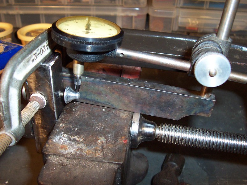
I then clamp the fixture to something solid. In this case a small anvil.

I then clamped the dial indicator in place.
Place the plunger at the 12:00 position on the end of the crank.
The stock prop nut is smooth and centers
well on the end of the crank so I installed it snuggly to give the dial
indicator a good surface to run against.
The key here is to have the dial indicator mounted solidly and to have
no play in the crank so that the dial indicator will measure only the bend
as the crank is rotated in the hole.
This crank showed to have .018" of total deflection.
Rotate the crank until maximum deflection is reached at the twelve o'clock position of rotation.
Use the rod pin to note the cranks position.
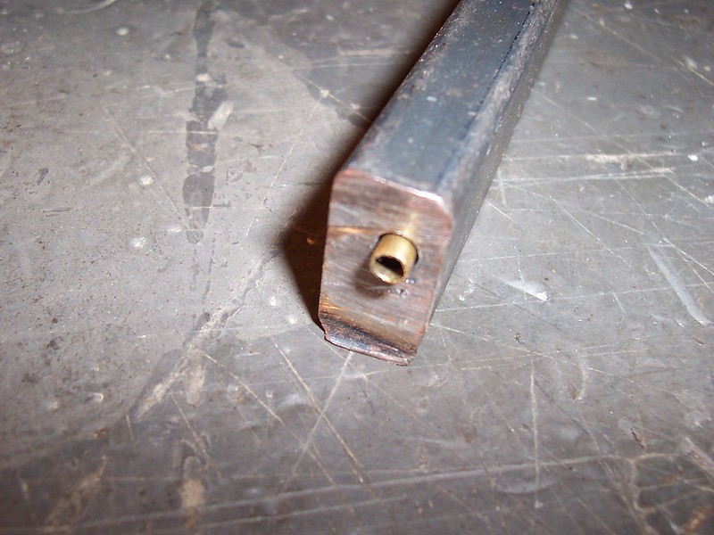
Next I made a tool to bend the crank with. I used a 1/2"X1"X6" piece of flat bar stock.
I drilled a hole that would accept a piece of brass tubing 1/2" long.
The tubing fits snuggly over the crank and protects the threads.
Making sure that max deflection is at the 12:00 position I then place the
bending tool over the end of the crank and put the dial indicator down on
the tool.
The total deflection was .018" so the crank needs to be bent .009" to make it straight.
Bend straight down to the 6:00 position.
Here the dial indicator actually only works as a guide as it is not in the
same location as it was when measuring the deflection.
It takes a bit of "feel" when making the bend.
I had to put the prop nut back on and recheck the deflection several times
before I got it straight.
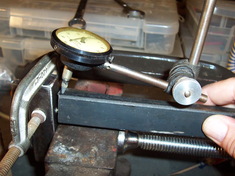
With the bending tool I got within .002" of total deflection.
I decided to give the crank a light tap with a small hammer
to move it the last .001". It took a several very light taps to get it.
Again, use brass tubing to protect threads.
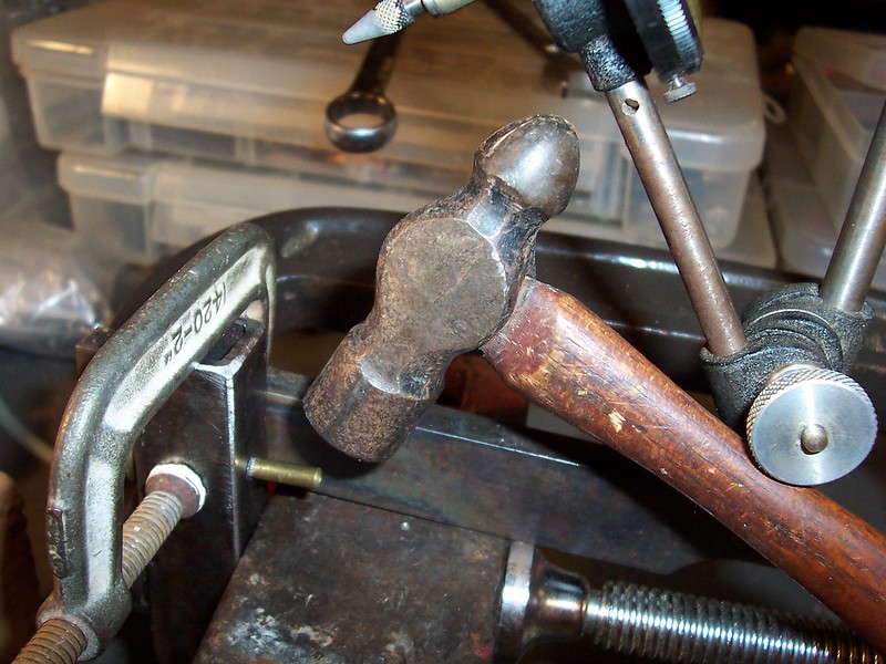
That is about it. Remember to be patient. Be gentle and careful with
the bends and check the deflection often.
You don't want to bend to far and have to bend back the other direction
or the crank is likely to break or seriously weaken.
I do still get a bit less than .001" deflection but felt that was close enough.
I balanced a prop, installed it and gave the engine a test run.
Ran very smooth with no problems.
I have straightened cranks on engine sizes up to .60.
The procedure was the same only the fixture and bending tools
were larger.
Thanks for reading!
Tom
